Question:
NOTE: Do NOT forget to check if the necessary keyways will result in excessive stress concentrations hence make your design unsafe.
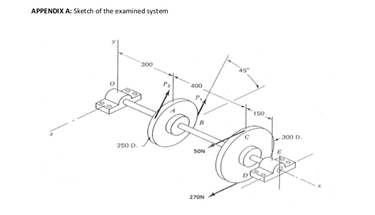
The shaft to be designed is part of a larger power transmission system, which is expected to operate in an environment of 35oC, for 16 hours per day and for 5 days per week. A level of 90% reliability should be considered, while the deflection of the shaft should be less than 1/500 of its length. The angular velocity of the shaft is 1500rpm and the shaft should be designed for infinite life, while all bearings if used, should be selected so that they may be replaced after at least 12,000 hours of operation. The shaft should be supported at its ends only. The design of the supports (i.e. type, size, etc) is free but you should fully justify your choice. Some additional information (e.g. length of the shaft, the location of pulleys, etc) is also shown in the given sketch. The distance between the given shaft and each one of the collaborating shafts is 1.5m.
a. Identification of parts
As a first step and based on the given sketch, identify the main parts of the examined system and briefly describe their operation. Define the sense of rotation of the shaft and identify whether each given pulley is a driving or a driven element.
b. Calculations of Power Transmission – Power Flow Diagram
For each one of the flat pulleys, calculate the respective power. For each one of the supports, identify if there is a power loss or not (and estimate the respective power). Taking into account all the calculations related to power transmission, draw a Power Flow Diagram and examine if there is power equilibrium.
IMPORTANT Hint: if a power loss due to friction is taken into account, what should P1 and P2 (see the sketch in Appendix A) be equal to?
c. Selection of a grooved pulley/V-belt system to replace the “Ø300 flat pulley”
Through a typical procedure for selecting a grooved pulley/V-belt system, find one that can replace the “Ø300 flat pulley”, shown in the sketch in Appendix A, and justify why your selection satisfies the given specifications.
d. Selection of a grooved pulley/V-belt system to replace the “Ø250 flat pulley”
Repeat the previous step for the “Ø250 flat pulley”, shown in the sketch in Appendix A, and justify why your selection satisfies the given specifications.
e. Design of shaft – Static analysis
Using dimensions and information you can retrieve from the given sketch (Appendix A of present assignment brief), as well as the grooved pulley/V-belt systems you have already selected, draw the Free Body Diagram of the examined system and proceed with a complete static analysis (i.e. calculate forces and moments exerted on the shaft by the pulley/belt systems, calculate the reaction forces at supports, calculate the necessary bending moment and shear force diagrams, calculate the resultant shear stress, define the required diameter of the shaft, etc). Conclude if your design is safe.
NOTE: Do NOT forget to include in your calculations the self-weight of the shaft and the self-weight of the pulley/belt systems.
f. Design of shaft – Fatigue analysis
Conduct a fatigue analysis of the shaft (e.g. calculate the midrange and the amplitude of involved stresses, consider various modification factors, apply a fatigue criterion, etc) and conclude if the Fatigue Factor of Safety of your design is acceptable.
g. Design of shaft – Deflection
Calculate the maximum deflection of the examined system and conclude if your design complies with the given deflection constraint.
h. Keys - Keyways
Using the respective British Standard, select the keys and keyways required to mount the grooved pulleys on the shaft.
i. Bearings Selection
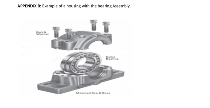
Use 'Timken' or 'SKF' variety bearings manufacturer catalogue to select the right bearings to fit the designed shaft & the bearing housing/shaft support. From the calculated nominal diameter of the shaft, decide on suitable shaft size tolerances so that they match the requirements of SKF for a stationary inner ring load.


ANSWER


NOTE: Do NOT forget to check if the necessary keyways will result in excessive stress concentrations hence make your design unsafe.


Comments
Post a Comment